Monday 31 December 2018

New source of answers from University of Utah

After finishing Exercise 2.07 I searched for other solutions and found on at the University of Utah for a course by Pearl Sandick in Spring 2018. They were using the book as their textbook. The home page for the course is here: http://www.physics.utah.edu/~sandick/7720spring2018/index.html. As ever I have saved the solutions in case they get deleted. I have catalogued the answers on the Answers to Exercises page.

I am glad to say that my answers to the exercise were correct.

Saturday 29 December 2018

Commentary 2.7 Causality

I think I found two errors in the book here, They are highlighted in red below.

Part 1 Causality jargon

This section was introducing a ton of jargon and, as ever, Carroll confused me with his brevity and power sentences. Early on we had an achronal hypersurface which is one where no two points are connected by a timelike curve. Carroll gives any edgeless spacelike hypersurface in Minkowski space as an example. I was having a bit of trouble imagining an 'edgeless spacelike hypersurface in Minkowski space' when I found Fig 1. That made it obvious. The HYPERSURFACE OF THE PRESENT therein is achronal.
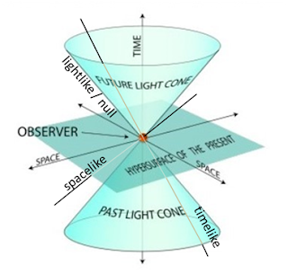
Fig 1
I was confused by the long noun phrase 'edgeless spacelike hypersurface in Minkowski space'. Thank heavens it was not in German, it might have been Minkowskistumpfraumsechthyperfläche. As a reminder we classify the following straight lines through the observer:

timelike
inside the light cone - massive particle
null (aka lightlike)
on the light cone - photon
spacelike
outside the light cone

On a flat (x,t) spacetime diagram any line is a hypersuface, if it's edgeless it continues forever and it is spacelike if its gradient m is always limited: -1 < m < 1 - it is more parallel to the space axis than the time axis.
Fig 2 Various types of hypersurface. Both spacelike surfaces are achronal.
The upper right 'hypersurface' is timelike, null and spacelike because it is steep at the left hand end and then shallow. The spacelike hypersurfaces are also achronal, they do not contain any points that are connected by a timelike curve.

Thinking about an achronal hypersurface S, Carroll defines one + four (or eight) new terms.
Causal curve

One which is timelike or null everywhere. Two are shown.
Causal future of S
J+(S)
Set of points that can be reached from S by following a future directed causal curve
Chronological future of S
I+(S)
Set of points that can be reached from S by following a future directed timelike curve
Future domain of dependence of S
D+(S)
Set of all points that p such that every past moving inextendible* causal curve through p intersects S. Points predictable from S (see below).
Future Cauchy horizon of S
H+(S)
Boundary of D+(S). Limit of predictable points (see below).
The other four definitions follow by exchanging past and future and + and -.

* inextendible means the curve goes on forever.

We'll now concentrate on the spacelike hypersurfaces S and T, which are achronal, in fig 3.

Fig 3
The futures of T are easy to visualise. It is also easy to see that p is in D+(S) and that q is not, so D+(S) is the interior of the 'triangle' with the wavy bottom bounded by two null surfaces.

Before all the definitions, Carroll had mysteriously said that "We look at the problem of evolving matter fields …".

Light dawned: The evolution from events (the initial conditions) in S can only completely specify future events in D+(S) its future domain of dependence. Events beyond its future Cauchy horizon cannot be predicted from the initial conditions.

There were some more terms

Cauchy surface
Closed achronal surface Σ whose domain of dependence D+(Σ) is the entire manifold
Globally hyperbolic
A space time that has a Cauchy surface
Partial Cauchy surface
? Cauchy surface whose domain of dependence D+(Σ) is not the entire manifold
Closed time like curve
See below

From information on a Cauchy surface on we can predict what happens throughout the entire manifold / entire universe / all spacetime.

Part 2. Cylindrical spacetime 

We then have a simple example: Consider a two-dimensional geometry with coordinates ##\{t , x\}##, such that points with coordinates  ##(t , x)## and ##(t , x+1)## are identified. The topology is thus ##\boldsymbol{\mathrm{R}}\times S^1##. We take the metric to be
$${ds}^2=-{\mathrm{cos} \left(\lambda \right)\ }{\mathrm{d}t}^2-{\mathrm{sin} \left(\lambda \right)\ }\left[\mathrm{d}t\mathrm{d}x+\mathrm{d}x\mathrm{d}t\right]+{\mathrm{cos} \left(\lambda \right)\ }{\mathrm{d}x}^2$$where$$\lambda ={{\mathrm{cot}}^{-1} t\ }$$which goes from ##\lambda  =0## (##t = - \infty ##) to ##\lambda  = \pi## (##t =  \infty ##).

##\lambda ={{\mathrm{cot}}^{-1} t\ }## is the same as ##\lambda ={\mathrm{tan}}^{-1} ( 1 / t )## and so
$$t=\ 1 /{\mathrm{tan} \lambda \ }$$That's a problem. As ##\lambda \to 0, t \to \infty ## not ##-\infty ##. So we really want
$$\lambda =-{{\mathrm{cot}}^{-1} t\ }$$To find the light cone we want a null vector ##V^{\mu }##, at various times. We can get this from the metric and Desmos plotted various light cones from 0 to ##\pi## as shown below. Details are in the pdf. I had arrived at the same diagram as Carroll!


Fig. 4. Shows the light cones in red  in the distant past (λ = 0) to distant future (λ = π). In our diagram we are identifying points with coordinates (t,x) and (t, x+~100), so that we can better see the strange light cones for large t or λ≈π .

Our light cones rotate the same way as Carroll's  Fig 2.25.

Carroll says "When t > 0, x becomes the timelike coordinate." (Because x, not t, is in the light cone. Moreover light and particles can only move in the positive x direction and they can move in + and - t directions.) We can now draw two causal curves from a point p as shown. One reaches the surface S, the other does not. Therefore p is outside the future Cauchy horizon of S. This applies to any point p with t > 0. As he says "There is thus necessarily a Cauchy horizon at t=0." Surely it's worse than that. There is a 'global' Cauchy horizon at t = 0. Perhaps that is what he meant.

In plainer language: "Nothing at t > 0 is predictable by things at t < 0".

I don't see why we had to have the cylindrical coordinate system. The closed causal curve guarantees that the causal curve from p is inextendible, but we could have had a curve that waved around forever keeping its t coordinate always >0.

Part 3 A singularity

There seems to be another error in the book here. His fig 2.26 shows a singularity at a point p and the text discusses a point p that is in the future of the singularity. So I will repeat the paragraph and the diagram using separate p's.

Fig 5
It starts clearly enough, "Singularities are points that are not in the manifold even though they can be reached by travelling along a geodesic for a finite distance. Typically they occur when the curvature becomes infinite at some point; if this happens, the point can no longer said to be part of space time." Now I take over.

Fig 5 shows a singularity at s and an achronal surface Σ that extends indefinitely in the plus and minus x directions. The point p cannot be in D+(Σ), future domain of dependence of Σ, because there are causal curves from p that end at s. Therefore there is a future Cauchy horizon at H+(Σ) as shown. H+(Σ) also extends indefinitely in the plus and minus x directions.

I am not sure if the right branch of the past light cone from p should escape the influence of the singularity, but it does not matter for this argument.

Part 4. A Diversion

From fig 4 it is clear that photons and particles from t > 0 can travel backward in time to t = 0 or nearby. Sadly I was not able to find the equations of motion. I need to know more about geodesics perhaps.

There is more detail about that and the equations in part 2 here: Commentary 2.7 Causality.pdf

Thursday 27 December 2018

Latex, Physics Forums, Desmos, Symbolab, MathJax, GrindEQ

This is somewhat out of date for me. I have now purchased GrindEQ Word->Latex, which is highly idiosyncratic and have written Word macros to greatly improve it. See XXXXX.

Latex is a script used to display equations on websites by Physics Forums, Desmos the grapher,  Symbolab the equation solver and this Blogger blog with MathJax. Latex is described on Physics Forums here and more completely by Mark Gates here. I also have some Latex tips here (MS-Word). I started by using something from Codecogs but it was not good at displaying inline equations (##\mu=0##) or adjusting the font size of indexed variables ( ##{\partial }_{\mu }y^{\alpha }## ) .

GrindEQ can save a word document containing equations as a .tex plain text file. This contains some non-Latex (for the MS-Word text) and bits of delimited Latex. So it it fairly easy to copy and paste the Latex to other websites. The only difference is in the characters that delimit the Latex. These are summarise below.

Format
Delimiter for
Delimiter
PF (website)
New line
$$

In line
##
.tex  (file from GrindEQ)
New line
\[

In line
$
MathJax
New line
$$

In line
$
Symbolab

none
Desmos

none

Here's something I wrote and pasted the RHS into Desmos and Symbolab.
$$ x = \frac{t\left(\sin \left(l\right)-1\right)}{\cos \left(l\right)} $$
You can copy and paste the Latex of the RHS directly into Desmos and Symbolab equations. It is

\frac{t\left(\sin \left(l\right)-1\right)}{\cos \left(l\right)}

Then I created a test Word document pictured below
Image from MS-word
And here is the same thing produced by GrindEQ and then pasted out of the .tex file into this blog.

So the pullback operator is (##\mu## is row index, ##\alpha## is column)

$$  {\partial }_{\mu }y^{\alpha }=\left( \begin{array}{cc} {\mathrm{cos} \theta \ } & {\mathrm {sin} \theta \ } \\ -r{\mathrm{sin} \theta \ } & r{\mathrm{cos} \theta \ } \end{array} \right) $$

$${\partial }_{\mu }y^{\alpha }\equiv \frac{\partial y^{\alpha }}{\partial x^{\mu }} =\left( \begin{array}{cc} \frac{\partial x}{\partial r} & \frac{\partial y}{\partial r} \\  \  & \  \\  \frac{\partial x}{\partial \theta } & \frac{\partial y}{\partial \theta } \end{array} \right)=\left( \begin{array}{cc} {\mathrm{cos} \theta \ } & {\mathrm{sin} \theta \ } \\  -r{\mathrm{sin} \theta \ } & r{\mathrm{cos} \theta \ } \end{array} \right)$$

or on the final equation using \Large , \large and \small (\normal does not work)

##{\partial }_{\mu }y^{\alpha }  \equiv  \Large  \frac{\partial y^{\alpha }}{\partial x^{\mu }} \Large =   \left( \begin{array}{cc} \frac{\partial x}{\partial r} & \frac{\partial y}{\partial r} \\  \  & \  \\  \frac{\partial x}{\partial \theta } & \frac{\partial y}{\partial \theta } \end{array} \right) \small= \left( \begin{array}{cc} {\mathrm{cos} \theta \ } & {\mathrm{sin} \theta \ } \\  -r{\mathrm{sin} \theta \ } & r{\mathrm{cos} \theta \ } \end{array} \right)##

Sadly I only get ten free uses of GrindEQ nd then I have to pay 50€.

Installing the mathjax code to show equations in Blogger is simple and instructions are contained here. However the page freezes shortly after opening and the Blogger instructions are out of date, so the vital parts are worth repeating:

To enable MathJax, just drop in the following code snippet after the header (<head>) in the Blogger template (Theme →Edit HTML→Edit Template). The the £ sign should be replaced with the dollar currency sign. It is hard to get that in the text here! The unadulterated code snippet is also in this text file.

<!--Script to enable Latex from http://web.archive.org/web/20110412103745/http://mnnttl.blogspot.com/2011/02/latex-on-blogger.html -->
<script type="text/javascript" src="http://cdn.mathjax.org/mathjax/latest/MathJax.js">
MathJax.Hub.Config({
 extensions: ["tex2jax.js","TeX/AMSmath.js","TeX/AMSsymbols.js"],
 jax: ["input/TeX", "output/HTML-CSS"],
 tex2jax: {
     inlineMath: [ ['£','£'], ["\\(","\\)"] ],
     displayMath: [ ['$$','$$'], ["\\[","\\]"] ],
 },
 "HTML-CSS": { availableFonts: ["TeX"] }
});
</script>

No doubt one could use different delimiters by changing the inlineMath and displayMath lines if one wanted.

Thursday 20 December 2018

Question on canonical for of the metric

I posted a question on the canonical for of the metric to physics forums here. It is about equation (2.46) in the book.  he writes:
Quote: A useful characterisation of the metric is obtained by putting gμν into its canonical form. In this form the metric components become
$$ g_{\mu\nu} = \rm{diag} (-1, -1,...-1,+1,+1, ... +1,0,0, ... ,0) $$
where "diag" means a diagonal matrix with the given elements. So Carroll's expression seems to imply a diagonal matrix with with a minimum size 9x9 and one extra row and column wherever one of his .'s takes a value. That's too vague!

There were two good answers and I would rewrite (2.46) as
$$ g_{\mu\nu} = \rm{diag} (-1, 0,1...-1, 0,1 ... -1, 0,1 ... -1, 0,1) $$
i.e. each diagonal element can be -1,0 or 1. 

Sadly Orodruin wrote "That would have been wrong and very unclear." He did not elucidate.
I then wrote:
Does this work?As a matrix, a non-degenerate metric in canonical form is diagonal with ±1 in each component.
Orodruin:
Technically, that would be a pseudo-metric unless you have +1 in all diagonals, but in physics we just call it metric anyway.
martinbn:
This
$$ g_{\mu\nu} =  \begin{pmatrix} -1 & 0 & 0 & 0 \\   0 & 1 & 0 & 0 \\   0 & 0 & 1 & 0 \\    0 & 0 & 0 & 1 \end{pmatrix} $$
and this
$$ g_{\mu\nu} = \rm{diag} (-1, 1, 1,1) $$ 
are the same.

I was tempted to reply Are we discussing how many angels can fit on a pinhead? But religion is not allowed.

So the canonical form of the R² metric is

$$ \begin{pmatrix} 1 & 0 \\   0 & 1  \\    \end{pmatrix} $$

and the canonical form of the Minkowski metric (which is Lorentzian) is

$$ \begin{pmatrix} -1 & 0 & 0 & 0 \\   0 & 1 & 0 & 0 \\   0 & 0 & 1 & 0 \\    0 & 0 & 0 & 1 \end{pmatrix} $$

Wednesday 19 December 2018

Symbolab differential equation solver

Click picture to enlarge
Symbolab is a godsend. 

In Exercise 2.06 I had a lot of differential equations to solve and inevitably made a few mistakes. 

Here's a sample. 

Click on it to make it bigger...

Or see the full text in Ex 2.06 Helix.pdf

Praise be to Symbolab!

Find them at https://www.symbolab.com/solver/ordinary-differential-equation-calculator

Monday 17 December 2018

3-D Graph plotter

The Excel has been up dated for this. It now has animation macros. It is at 3-D graph plotter.xlsm. The new animations are in 3-D Graph plotter Version 2.... Read on.

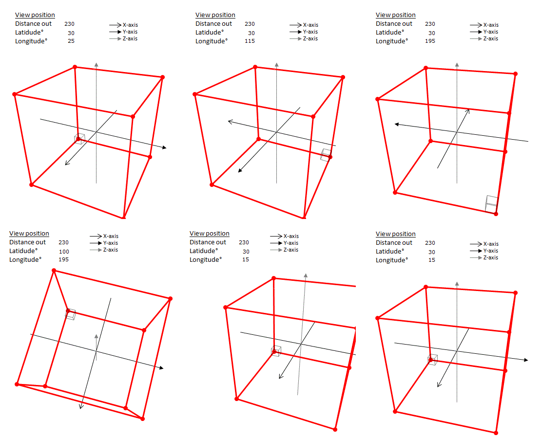
I was doing exercise 2.06 in the book which was about a helix. I plotted the helix using Excel in a rather ad-hoc way. I wanted something better and more general so that I could plot any 3-D line on a view plane from the point of some viewer outside the view plane. I did it. Here is an animation of orbiting a big cube (100x100x100) and a small cube (10x10x10). The big cube is centred on the origin and so its bottom corner is at (-50.-50,-50). The small cube's bottom corner is at the same point, so we can easily locate the bottom corner of the big cube.
Orbiting a cube

The cubes are being viewed from a distance out of 230. The view moves in three phases:

1) The viewer moves from latitude 30°, longitude from 25° to 195° when after a short pause ...

2) Her longitude is held at 195° and her latitude increases over the North pole. There is a pause at 89.9° and 90.1°. (90° cannot be shown), At this stage the Z-axis has disappeared and the X- and Y-axes flip. Latitude 150°, longitude 195° is the same as latitude 30°, longitude from 15°. The viewer is almost back where she started.

3) Next there is a jolt as the direction of view changes from the origin to the centre of the small cube. Our intrepid viewer zooms in to distance of 100 and then back out to 230. The cycle repeats.

To get a more controlled journey round the sphere, you click here. You should see a list of the little gifs that make up the one shown here. Double click one and you can go through them like a slide show at your own speed.

The spreadsheet produces one image at a time, the animation was made with MS-Paint and GIF Animator. The Excel spreadsheet is at 3-D graph plotter.xlsx. It requires some expertise in Excel and scatter charts to use. It might be best to read the first two pages of 3-D graph plotter.pdf which give some instructions. The other 18 are devoted to developing and testing the Excel formulas needed.

A helix. The bottom quarter strand is red.


And here is the helix. It has radius 70 and goes up 2π every revolution. It appears to bend slightly around the Y-axis, but this is just a perspective effect.

This was my first excursion into 3-D Cartesian geometry and I was helped by the equations for lines and planes at https://brilliant.org


Thursday 6 December 2018

Exercise 2.06 Helix and tangent vector in Cartesian and spherical polar

Question

Consider R³ as a manifold with the flat Euclidean metric, and coordinates {x, y, z}. Introduce spherical polar coordinates {r, θ, ϕ} related to {x, y, z} by
x = rsin⁡θcosϕ (1)
y = rsin⁡θsin⁡ϕ (2)
z = rcos⁡θ (3)
so that the metric takes the form
ds2 = dr2 + r2dθ2 + r2sin2θdϕ2 (4)

(a) A particle moves along a parameterised curve given by

x(λ) = cos⁡λ  y(λ) = sin⁡λ  ,   z(λ) = λ (5)

Express the path of the curve in the {r, θ, ϕ} system.

(b) Calculate the components of the tangent vector to the curve in both the Cartesian and spherical polar coordinates.

Answers

It is fairly obvious that the curve is a helix. It has unit radius, the distance between each rung is 2π and so it goes up at an angle of 45°. It is shown below, compressed in the Z direction.
The helix, with some vector components

Calculating the components of the tangent vector d/dλ in polar coordinates was non-trivial for me. It involved the chain, the quotient and the cos-1 rules of differentiation. I checked them by using the tensor transformation law from Cartesian to spherical polar components. The law is


In this case b…z and α...ω indices disappear, so it became a bit simpler but there were still almost 50 equations to step through and I had to add the tan-1 rule of differentiation to my armoury. I discovered that this method gave a different result for dθ/dλ component of my tangent vector. The possibility of errors had became enormous. Symbolab, a wonderful differential equation calculator, came to my rescue and I used it to check everything. It discovered a couple of minor errors in my 50 equation epic, but eventually pinned down the error to the first calculation of dθ/dλ from the equation of the curve in the {r, θ, ϕ} system. It just goes to show how important it is to have an 'independent' check.

More Gains

1) I have also now realised why the metric is sometimes written in the form like

ds2 = dr2 + r2dθ2 + r2sin2θdϕ2

and sometimes as a matrix. And how to get from one to the other.

2) In oder to draw the helix, I developed a spreadsheet to draw the 3-D curve. I am inspired to do something more general to draw any 3-D curves from a specified perspective.

The full 11 page answer is at Ex 2.06 Helix.pdf. It includes a reference to the spreadsheet and from page 6 is mostly Differentiation in baby steps and other detailed calculations.

Wednesday 28 November 2018

Commentary 2.6 Expanding Universe

In section 2.6 we met a special case of the Robertson-Walker metric for an expanding Universe. Exciting! The section was a 'playground' for our previous work. From the metric we got to
0 < q < 1. Even I could integrate that equation, but Carroll produced
by changing the variables around. As you really want how x changes as t progresses, the obvious equation
is much more informative and useful. x0 is a constant of integration, in fact where our test photon starts.

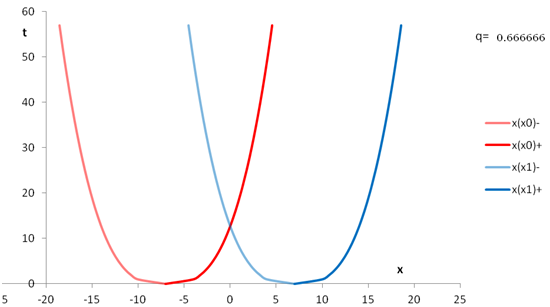
I could then get some graphs and understand what he was talking about. t must be positive. (One can't take a fractional power of a negative number.)
Two light cones
x0  is the point on the X axis where the light cone starts. The red x(xo) lines are the solutions for x0 = -7 the one on the left (paler) being the negative part. The x(x1) lines are for x0 = 7. The light cones always and only intersect at some t > 0 midway between their start points. There are no solutions for t < 0.

If we set q = 0 then we get our flat Minkowski space and we can have t < 0. The diagram becomes
Light cones in Minkowski spacetime 

The light cones intersect in the past (bottom open triangle) as well as in the future (top open triangle).

In the spirit of the playground, it is amusing to show the first diagram again with (impossible) t < 0. Excel does a great job!
Big Bang

Read in more detail at Commentary 2.6 Expanding Universe.pdf. Includes link to spreadsheet.

Monday 26 November 2018

Commentary 2.5 Metric, Rocket and 4-velocity (four-velocity)

The observer, abandoned by the rocket.
Before equation (2.51) near the end of section 2.5, Carroll writes: "Take a very simple example, featuring an observer with four-velocity U and a rocket flying past with 4-velocity V. What does the observer measure as the ordinary three-velocity, v, of the rocket? In special relativity the answer is straightforward. Work in inertial coordinates (globally not locally) such that the observer is in the rest frame and the rocket is moving along the x-axis. Then the four-velocity of the observer is
Uμ  =  (1 , 0 , 0 , 0) 
and the four-velocity of the rocket is
Vμ =(γ , γv , 0 , 0)
where v is the three-velocity and
γ = 1 / (√(1 - v2 ) ) 
so that
= √(1 - γ-2)
"

It is easy enough to understand the first and last equations but the two middle ones were not so easy.

His (2.51) itself starts
γ =  -ημν UμVν
"since η00 = -1"

that seems to come out of nowhere and had me thinking.

It all ends well with the gloriously tensorial equation

v = √(1 - (Uν Vν)2 )

which allows me to proceed to section 2.6 on An Expanding Universe!


I reviewed this June 2021 and realised that this is really an example of  Riemann normal coordinates which is super useful! Details in the pdf, I have not modified this very old, rather quaint post.

Saturday 24 November 2018

Commentary 2.4 Tensors again - transformation law for general tensors

In section 2.4 the we meet the powerful but intimidating transformation law for general tensors (his 2.30)

that is followed by a simple example with a rank (0,2) tensor in a 2 dimensional coordinate system with a transformation to another 2 dimensional system. He derived the the transformed tensor without using the above law but encouraged us to do so and see if the answer was the same. I did and it was. The tensors and the transformation become much simpler and comprehensible.

I also explained more about his equations on the way, including where the missing ⨂'s were, and tried to simplify the transformation law. Putting the primes higher up in the chain helps a bit:


but that was as far as it went.

Read it all 3 pages here at Commentary 2.4 Tensors again.pdf

Thursday 22 November 2018

Rules for tensors, matrices and indices

This all started because I was confused about the difference between co- and contra-variant vectors and how to turn tensors into matrices. There seemed to be conflicting definitions, most of which I have now resolved. The exploration took me almost two months, when I intended a few days. I have learnt a lot.

During the two months I created some word macros to help write 211 equations.I also heavily revised Exercise 1.07 Tensors and VectorsCommentary on Appendix A: Mapping S2 and R3 and had a lively discussion on Physics Forums: Question on co- / contra-variant coordinates.

I have now found about 25 useful rules for tensors, vectors, indices and matrices. They come first, then many notes and examples finally a contents at the end.

The rules

  1. A tensor of type (or rank) (k , l) has k upper indices and l lower indices.
  2. If we just say a tensor has rank z, we are being a bit vague: z = k + l.
  3. A scalar is a type (0,0) tensor. Scalars are invariant under coordinate changes.
  4. A vector (or contravariant vector) is a type (1,0) tensor, e.g. i . Each i is a component of the vector V.
  5. A dual vector (or one-form or covariant vector or covector) is a type (0,1) tensor, e.g. ωi
  6. Upper indices are co↑travariant, lower indices are co↓ariant.
  7. Both kinds of vectors can be written as column or row matrices.
  8. When we say a vector is covariant or contravariant we really mean its components are covariant or contravariant. A vector is invariant under coordinate changes. Its components are not. Therefore length and velocity are not real vectors in Minkowski spacetime.
  9. A rank 2 tensor can be written as a two dimensional matrix. Components must be written so that the first index indicates row components and the second index column components. Whether the indices are up or down is irrelevant for this rule.
  10. By 'contracting' two tensors Ti l , R k j we mean multiplying and adding components, e.g. l, k. We would write this Ti l , R l j which would produce Xi j. This is most easily done by multiplying the matrices T, R or  Ti l , R k j . Subject to these rules: 
    • When converting tensors to matrices for multiplication the summed indices must be last and first (or adjacent): Ti Rk j  not Ti k  R j k . Ti k  R j k   can be calculated without matrices but it's horrid. 
    • If you know the matrix T for a rank 2 tensor Ti k, then the matrix of the tensor with indices reversed k i is the transpose of T or TT .
    • You can only contract upper and lower indices. Contracting two upper or two lower indices would give something that is not a proper tensor.
    • The 3 bullets above even apply to the partial derivative matrix jai .. 
    • The metric ημν  is a type (0,2) tensor and it lowers an index.
      The inverse metric ημν raises an index.
      η μν ηνκ  = δ μκ  , the Kronecker delta (identity matrix).
      Replace η by g when in curved spacetime. 
    • The order of the tensors does not matter (unlike matrices). Ti k R j  = R k j Ti k always. TR = RT rarely. The same applies for tensors of any rank including vectors. 
  11. Co-/contra- variant vector components combined give correct magnitude (length) and dot products.
    • Norm (=length²): |v= ημν  Vν Vμ  = Vμ Vμ . 
    • Dot product: v∙w = ημν  Vν  Wμ  = Vμ  Wμ . 
    • The 2 bullets above only work on flat manifolds (all ημν are constant). 
  12. More tensor rules 
    • Raising or lowering an index does not change its left-right order. Free indices must be the same on both sides of the equation. Dummy indices only appear on one side of the equation - they are being summed over.
      Correct: αβμ δ = η μγ T αβ γδ .
      Wrong: T αβδ μ  = η μγ T αβ γδ . Indices changed order.
      Wrong: αβμθ  η μγ αβ γδ . Free indices not the same.
      Wrong: αβμγ  η μγ αβ γδ. Dummy index on both sides. 
    • You may raise and lower dummy indices simultaneously: λ Bλ   = Aσ B σ 
    • There are yet more rules. 
For these rules and over 34 pages of examples and notes see
Commentary 1.1 Tensors matrices and indexes.pdf.

Monday 12 November 2018

Question on co- / contra-variant coordinates

I am studying co- and contra- variant vectors and I found the video at https://www.youtube.com/watch?v=8vBfTyBPu-4 very useful. It discusses the slanted coordinate system where the X, Y axes are at an angle of α. One can get the components of v either by dropping perpendiculars to the axes (vi) or by dropping a line parallel to the other axis (vi). These give correct results for the norm vi vi and the dot product vi wi. (I have not shown w). So the vi are called contravariant and the vi are called covariant. According to the video Dirac thought this was a great example.

But both vi and vi  contra-vary with a change of scale of the basis vectors. This contradicts some definitions of contravariant and covariant components, e.g. this one on Wikipedia. These definitions say that covariant components co-vary with a change of scale.

Is there a simple resolution to this apparent contradiction?

Submitted as comment on video and
on Physics Forums at https://www.physicsforums.com/threads/covariant-coordinates-dont-co-vary.959888/

Orodruin answered on PF seven hours later with "The covariant and contravariant components belong to different basis vectors." Cryo came up with something a bit more complicated and I followed Orodruin. So here's how it goes:

To get v with the covariant coordinates we must have
v = vxex + vyey      (1)
I have drawn them in on the diagram and ex is clearly smaller than ex, which I have conveniently drawn so that vx = 1. We must also have
 vxex = vxex       (2)
and similarly
vyey = vyey       (3)
which give us
v = vxex + vyey       (4)
which is as it should be.
(3) gives us
vy = ey(ey)-1vy       (5)
where (ey)-1 is the inverse of ey: or ey(ey)-1 = 1.

(5) shows us that vy does indeed vary with ey with a strange constant of proportionality (ey)-1vy.

Back to the drawing board

Orodruin did not like that at his #5 and then gave me a tip at #7 that the dual (or covariant) bases are given by êa = ∇xa. I will use ê for basis vectors in future, following Carroll. From the formula I could calculate the covariant basis vectors in terms of the Cartesian basis vectors because I already had the inverse metric of the covariant system. This was calculated from the transformations of the systems to and from Cartesian.

The answer came:

and draw them properly (x = 1, y = 2)
From (NF12) it is clear that  êx is π/2 - α below the Cartesian X axis. Therefore the angle between êy and êx is a right angle, and the projected line from vy  is parallel to êx as we should have guessed and Orodruin intimated. Likewise êy is parallel to the projected line from vx and always on the Cartesian Y axis. In addition |êi | > |êi |.

Getting back to the original question, what happens to vx if we double the contravariant basis êx to ê'x? We could leave  vx, êx, vy, êy alone and they would still give v. We could double êx and halve vx. Neither option would co-vary. Both would give incorrect values for |v|. We need to find the metric of the primed system so we can just calculate the primed covariant coordinates and bases. We also cannot use the previous technique (calculating from the transformations of the systems to and from Cartesian), because we don't know how to transform primed covariant coordinates to Cartesian - we don't know what the primed coordinates are.

Therefore we use the pullback operator which we met two posts ago in Commentary on Appendix A: Mapping S2 and R3.

If we have our contravariant primed bases, with scale factors a,b so
ê'x = aêx  ,  ê'y = bêy 
which give
v'x  = vx  ⁄ a   ,  v'y =vy  ⁄ b 

Turning all the handles we end up with

v'x = a2v'x  + abv'ycos⁡α
v'y =b2v'y + abv'xcos⁡α

Since v' i  decrease as a, b and v'i  increase as a2  ,b2 ,ab, we can safely say that v'i  increase as êi . They co-vary. It also looks as if they will 'compensate' for v' i , giving correct |v| and v.w. We would just have to follow the trail.

The full details of all the above are contained in sections 5b and Note F of  Commentary 1.1 Tensors matrices and indexes.pdf

Wednesday 10 October 2018

Word Macros for equations

I have been copying and pasting tables and equations in MS-Word for far too long. At last I have written some word macros to speed things up, so I can more easily produce correctly aligned equations like
Fig 1: Aligning equation numbers neatly using 2 x 1 tables
and
Fig: LHS of equations unchanged and aligning equation numbers
I also wrote macros to create left / centre / right justified equations using font size 12 instead of 10 which MS always uses and I find too small.

So I now have a "Quick access toolbar" like this

After the AB icon, they have the following effects
  1. Select table
  2. Add bars on table
  3. Remove bars from table
  4. Make table a box. 
  5. Insert left justified equation (font size 12)
  6. Insert unbarred 2 x 1 table with centred justified equation in column 1, (xx) in column 2 (Fig 1)
  7. Insert unbarred 3 x 1 with right justified equation in column 1, (xx) in column 3 (Fig 2)
The first four are very useful for quickly sorting problems with tables and tidying them. They are all linked directly to MS-Word commands. 5-7 are linked to the macros. Sadly the equation insertion macros cannot be used twice the table creation macros! Therefore we also need icon 5, π, to manually insert the equation in the middle column of the three column table.

The macros are in WordBasic not VBA which is a bit amateurish, but WordBasic is what the Word macro recorder writes.

If you would like to use these macros click Read more and copy and paste them into the Word Visual Basic editor on the Developer tab.

The version in Read more might be out of date. I am fairly diligent about keeping back up versions here.

Friday 28 September 2018

Commentary on Appendix A: Mapping S2 and R3

Sometimes I almost despair reading this book. I cannot understand part of it or find a solution. When I do, the feeling of joy is superb. There is much air punching. This is a case in point.

Why am I here?

I'm still thinking about commutators and wanted to understand Appendix B on Diffeomorphisms and Lie Derivatives. Lie (pronounced lee) brackets are the same as commutators. Appendix B starts by saying "we continue the explorations of the previous Appendix", so I was thrown back. Appendix A is fairly comprehensible and there is a good example at the end. I'll restate the first part here:

The problem part 1

Consider the two-sphere embedded in 3, thought of as the locus of points a unit distance from the origin. If we put coordinates θ, ф on S2 (the sphere) and x,y,z on 3, the map  is given by

ψ (θ, ф) = (sinθ cosф, sinθ sinф, cosθ)          (1)

In the book this equation is written as
    ф(θ, ф) = (sinθ cosф, sinθ sinф, cosθ)            (A.11)
ф is used in the equation to mean a map and a coordinate. I will avoid this.

Sticking the sphere into  in this way induces a metric on , which is just the pull-back of the flat-space metric. The simple-minded way to find this is to start with the metric

             ds² = dx² + dy² + dz²                               (1a)

and substitute (1) into this expression yielding a metric dθ² + sin²θ dф² on .

This was not so simple and I struggled with the substitution for days. (1) is easy to show algebraically or geometrically. Getting to the metric in polar coordinates involves various differentiation rules: (trig functions and the product rule), but then they need to be applied to infinitesimals (dx, dθ etc) rather than proper derivatives (dx/dy etc). That aspect was very novel to me.


Along the way I made an interesting observation about writing the matrix for xyα. It is the transpose of the matrix for xyα. I will add this to my up coming opus on Tensors, Matrices and Indexes.

Five pages. You can read it here: Commentary App A Mapping S2 and R3.pdf

It contains a very useful corollary

It contains a very useful corollary on how to get the metric of a non-Cartesian system.
If we can transform non-Cartesian components j into Cartesiani with equations

i = f i (p j)                                                (20)
i = 1..m,   j = 1..n 

Then we can construct the (n x m) pullback operator


Multiplying this by its transpose gives the metric of the non-Cartesian system. 

Of necessity this is a (n x m) x (m x n) = (n x n) matrix, as it must be.